Grp has announced that production of the 2013 Series of the Grp A4 Synthesizer will start June 1st and that ordering will remain open until that date.
Here’s what Grp has to say about the A4 Synthesizer:
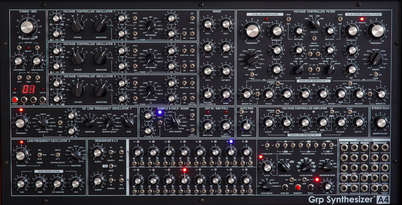
The A4 has been derived from an audio section of the Grp A8 (of which it takes over the structure) and it results more versatile and eclectic passing from smooth and extreme clean sonorities to harder sounds thanks to the two distortion installed in the synth (one for each filter) and due to the possibility to make interact synth, ring modulator, external signals and step sequencer in only on mechanism with an immense sonority power. Furthermore, the Loop EG function enables the conditioned and unconditioned repetition of the envelope, in order to reach particular and temporal articulated sonorities.
Details on the A4 Synthesizer below.
- Voltage Controlled Oscillator 1, 2, 3
- Wide audio range (64’-2’) w. Tune & Fine; six analog waveforms (sine, triangle, triangle & saw, saw, saw & variable pulse summed, variable pulse); manual pw & pwm (from VCLFO1, EG1, S&H, Aft); FM 1 Amt (lin/exp –from VCLFO1, LFO2, VCO1, 2, 3, Noise, S&H, EG1, EG2, Aft, ModW, KeyVel, EnvFoll) w. phase rev; FM 2 Amt (only exp – from VCLFO1, Env Foll); sub oscillator (on VCO 1, 2) -1/-2 oct; hard sync (VCO 1 master); kybd on/off (w. user’s selectable octave offset from MIDI Interface).
- Ring Modulator
- Ring Mod Sources: VCO 2 & VCO 3/Ext Input (user’s selectable).
- Noise Generator
- White & Pink Noise selectable.
- External Input
- Input gain from line to mic level; freely adjustable Gate Threshold (Gate to EG 1-2); enclosed envelope follower (goes into mod buss).
- Audio Mixer
- Separate level controls for VCO 1, 2, 3, Sub 1, 2, Ext Input, Ring Mod, Noise.
- Filter Section
- Dual analog filter section: 24 db/Oct Low Pass Transistor Ladder Filter w. pole selection & 12 dB/Oct State Variable Low, Band, High, Notch Filter.
- Each filter has a separate Distortion/Level control.
- Filter section can be configured in LP 24 Only, SV 12Only, Serial (LP into SV), Parallel, Direct Out (LP 24 goes on Left Audio Out, SV 12 goes on Right Audio Out).
- Low Pass Filter:
- Slope selection (6, 12, 18, 24 dB); Cutoff Frequency; Resonance; Overload LED; FM1 Amt (from VCLFO1, LFO2, VCO 1, 2, 3 Env Foll, Noise, S&H, EG2, Aft, ModW, KeyVel) w, phase rev.; FM 2 Amt (from VCLFO 1); FM 3 Amt (from Step Sequencer, Kybd Track 0-120%; Key Vel On/Off.
- State Variable Filter:
- Mode (12dB HP, 6 dB BP, 12 dB LP, 6 dB Notch); Cutoff Frequency; Resonance; Overload LED; FM1 Amt (from VCLFO1, LFO2, VCO 1, 2, 3 Env Foll, Noise, S&H, EG2, Aft, ModW, KeyVel) w, phase rev.; FM 2 Amt (from VCLFO 1); FM 3 Amt (from Step Sequencer, Kybd Track 0-120%; Key Vel On/Off.
- Voltage Controlled Amplifier
- Dedicaded Envelope Generator (see below); Control Selection (dedicated EG2, ON-hold, External CV); VCLFO1 Amt.
- AutoPan
- AutoPan Off/Internal Clock/VCLFO1; Pan Frequency Control; LED (red = internal clock; blue = VCLFO1).
- Stereo Main
- Master Volume.
- Envelope Generator 1
- Multi Stage Loopable Env (Attack, Hold, Decay, Sustain Lev, Sustain Time-Only in Loop On, Release); Gate Source Selection (Keyboard, S&H, ExtIn/ Step Seq); independent EG Amt for 24 dB LP Filter and 12 dB State Variable Filter, both w. user’s selectable EG polarity.
- EG time goes from 1msec to 20 sec.
- LED: red = EG under Gate sources; blue = EG under Step Sequencer control;
- Loop Envelope: loop from Attack to Release, w. Sustain Time selectable.
- Loop Mode Switch:
- Loop Off: EG as standard AHDSR, no Sustain Time.
- Gate: EG loops from A to S (w. Sustain Time max 60”) as long as Gate is On.
- Auto: EG full loop, from A to R; independent from Gate.
- Envelope Generator 2
- Same as EG 1, without Hold segment.
- Voltage Controlled Low Frequency 1
- Frequency (from very low to 2500 Hz); Waveform (sine, ramp, triangle, saw, square w. variable pulse); FM Amt (exp, w. phase normal/rev); FM Sources (Key, EG1, EG2, LFO2, Seq A, B, A+B, S&H, Aft, ModW, EnvFoll); Sync (Off, Gate, Seq, MIDI – dividing factor selectable from internal MIDI Interface); Shaping LFO out (from: Off, EG1, EG2, Lfo2, SeqA, B, A+B, S&H, Aft, ModW, EnvFoll).
- LFO act as modulation buss for auxiliary sources: EG1, EG2, S&H, Noise, VCO2, EnvFoll. The aux source can be amplitude modulated with the Shaping Select.
- Voltage Controlled Low Frequency 2
- Frequency; Freq Range (Low-Mid-High); Waveform (Triangle, Square); Shaping Select (Off, Aft, ModW).
- Independent Send Modulations for: VCO 1, 2, 3 freq; PWM 1, 2, 3; VCF 24/12 Cutoff; VCA Level.
- Sample & Hold
- Frequency; Frequency Source (Int, VCLFO1); LED (red = Internal, blue = VCLFO1); S&H Source (Pink Noise, White Noise, VCLFO 1, LFO 2, VCO 1, 2, 3); Glide.
- The S&H Clock can be routed to EG firing; there are three options: Off – no routing; Gate – the S&H clock is ANDed with keyb/ext/manual Gate; Auto – EGs always fired from S&H.
- Tuning/MIDI
- Master Tune; Portamento Time; Bend Amount; VCO 1 Portamento On/Off, VCO 1, Bend On/Off; Hold On/Off; A440 On/Off; Retrig On/Off; Manual Gate.
- MIDI Interface: MIDI Channel Select; Keyboard Off Octave Offset; External CV In Octave Offset; MIDI Clock Divider on LFO Reset.
- A4 receives: MIDI Note On/Off, Bend, Modulation, Aftertouch, Key Velocity, Expression Pedal, Damper.
- Step Sequencer
- User’s configurable Mode Select 8×2 or 16×1.
- Clock Source: Int, VCLFO1, Ext, MIDI.
- Clock Divider on all Clock Sources; dividing factor MIDI: 1/1, ¼, 1/4t, 1/8, 1/8t, 1/16; dividing factor TTL: 1/1, /2, /4, /16, /32.
- Sequencer Mode: FW, BW, FW/BW, PNDL, ALT, RND, TRG.
- CV Seq Clock: A, Off, B on internal Clock.
- VCO Seq Enable: VCO 1, 2, 3, Off/A/B/A+B
- VCF Seq Enable: 24dB Off/A/B/A+B; 12dB Off/A/B/A+B.
- Step Repeat: Off, x2, x3, x4.
- Permutations: n,n+1; n, n+1, n; n, n, n+1, n.
- Loop On/Off.
- Hold On/Off.
- Manual Controls: Reset/Step Advance, Run/Stop, Continue
- Pulse Width (legato/staccato) on Internal & MIDI Clock.
- Row A & B Parameters: Glide Amt; Range (x2, x4, x8); Quantizer On/Off.
- Step Parameters: LED; Step Value; Gate On/Off; Step Mode (End, Skip, Normal).
- Connections
- Audio: Mono Out; Phones Out; Left/24dB Out; Right/12 dB Out; Audio External In.
- Filter: CV In 24 dB; CV In 12 dB.
- Amplifer: CV In VCA.
- Synth Control: CV In; Gate In.
- External Modulation Buss: Ext 1/AftT; Ext 2/ModW.
- Sequencer Connections: Row A/B/A+B CV Out; Row A/B/A+B Gate Out; Run/Stop In; Continue In; Loop On/Off In; Clock Input; Clock Output; CV In Clock Modulation.
The Grp A4 Synthesizer is priced a 3667 Euro plus VAT. See the Grp site for details.

I gotta say that looks like a lot of synth for the price. Good on em!
That IS a lot of synth for the price. It’s starting to push the capabilities of a pretty nice modular setup. Has anyone played with a GRP? What’s the routing like? (I’m going to download some info from their site.)
that is a rather epic beast
Yeah, it looks pretty interesting, but that’s a lot of coin. But you could create a hell of a nice modular for that much money and probably match it feature for feature. And have the ability to mess with the signal and modulation paths. And be able to customize/vary VCOs, filters, etc., based on your own tastes. And build it up over time if you don’t have all the money up front. I guess it depends on whether you like screwing around with wires, or prefer something with a consistent design and pre-set architecture.
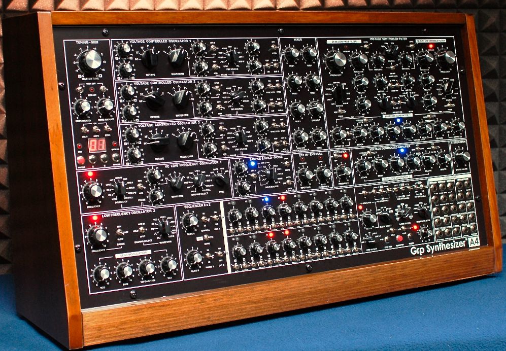
Someone made a serious knob-warehouse heist.
I’m not a designer, but… you could have a few patch cord outlets and inlets on the modules for a lot more flexibility and perhaps fewer knobs.
Eg, the LFO has 4 knobs each controlling output level to 4 hardcoded paths (incl VCO),
THEN the VCO’s have a knob to select among 10+ FM sources (incl LFO)
AND the VCO’s have an amount knob for the FM input.
This seems a slightly convoluted signal path.
Now of course I’ve nothing against convoluted, some of my best patches are fairly convoluted…
There’s a small patch bay down at the bottom right, I can’t read the labels in the picture though so I’m not sure what the options are.
Checked out the vids on their homepage.
#2 is interesting, shows the 2×8 step sequencers with several modes: serial, alternating, and “permutations”, playing steps with repeats and jumps in a structured way.
Musical and a good idea – takes Berlin style to the next level!
My friend has Both A8 and A4, he loves them and says its worth the money, i will order one as they do love and sound very nice