Red Rock Sound has released RED 70 – a classic electromusical synthesizer Rack Extension for Reason.
According to the developer, it does not recreate any specific synth, but it was ‘based on several classic synthesizers’.
Here’s a video intro:
Red 70 is available now in the Propellerhead Shop for US $49. Details below.
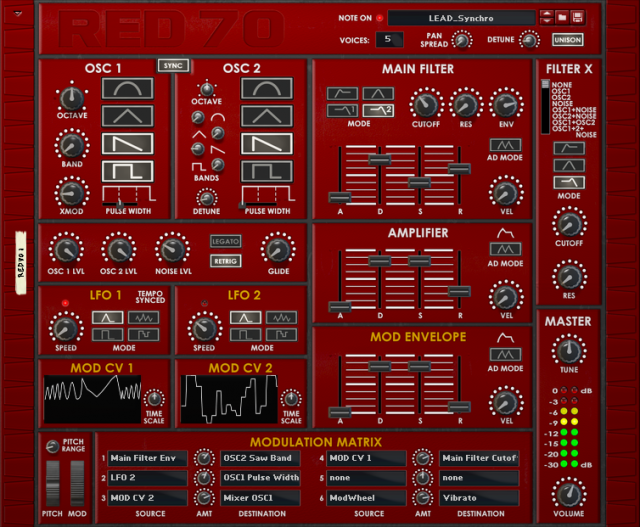
SYNTH SECTIONS:
OSC1
1. OCTAVE determines the pitch base. (two octave down and two octaves up from the main).
2. BAND Frequency band regulator.
3. XMOD Cross-modulation of the Frequencys of 2 Oscillators.
4. WAVEFORMS Four waveforms (sine, triangle, saw, pulse) with the ability to activate all of the waveforms simultaneously.
5. PULSE WIDTH controls the pulse width. (Pulse waves only)
6. SYNC synchronizes the triggering the OSC 2 waveform by the rate of OSC 1. When activated, OSC 2 BANDS controls affect only OSC 2 timbre, not its pitch.
OSC2
7. OCTAVE determines the pitch base. (two octave down and two octaves up from the main)
8. BAND Frequency band regulator for each waveform separately.
9. DETUNE detuning of oscillator 2 relative to the oscillator 1.
10. WAVEFORMS Four waveforms (sine, triangle, saw, pulse) with the ability to activate all of the waveforms simultaneously.
11. PULSE WIDTH controls the pulse width. (Pulse waves only)
ADDITIONAL OSCILLATORS & MIX SECTION
12. OSC1 LVL level control for the OSC1.
13. OSC2 LVL level control for the OSC2.
14. NOISE LVL level control for the noise generator.
15. LEGATO/RETRIG:
RETRIG controls envelope re-triggering. When activated, every note restarts the envelopes. (mode is clearly audible with 1-2 voices) In contrast to the RETRIG mode where every new note rearticulates the sound by restarting the envelope generators, in LEGATO mode the envelopes are not re-triggered if the new note is played “legato” (with the previous note still depressed). This causes the initial transient from the attack and decay phases to sound only once for an entire legato sequence of notes. Envelopes reaching the sustain stage remain there until the final note is released.
16. GLIDE determines the pitch sliding from one note to another.
FILTER X (Pre-filter, located ahead of the main filter.)
17. This switch selects a sound source to be processed by the filter: – OSC1 – OSC2 – NOISE – OSC1 + NOISE – OSC2 + NOISE – OSC1 + OSC2 – OSC1 + OSC2 + NOISE
18. MODE determines the filter type: – High Pass – Band Pass – Low Pass
19. CUTOFF controls the FILTER X cutoff frequency.
20. RES controls the amount of filter resonance.
MAIN FILTER
21. MODE determines the filter type: – High Pass – Band Pass – Low Pass 1 – Low Pass 2
22. CUTOFF controls the VCF cutoff frequency.
23. RES controls the amount of filter resonance.
24. ENV determines the envelope’s cutoff modulation depth. (You can set positive or negative values)
25. ADSR determines the filter’s envelope cutoff behavior after a note is triggered. – A (Attack) – D (Decay) – S (Sustain) – R (Release)
26. AD MODE The ADSR envelope switches to repeating Attack-Decay envelope.
27. VEL sets the envelope depth in relation to the Note On velocity.
AMPLIFIER
28. ADSR The VCA envelope controls the note level from trigger to release. – A (Attack) – D (Decay) – S (Sustain) – R (Release)
29. AD MODE The ADSR envelope switches to repeating Attack-Decay envelope.
30. VEL sets the envelope depth in relation to the Note On velocity.
MODULATION SECTIONS:
MOD ENVELOPE
31. ADSR The ADSR envelope generator that can be freely assigned to selectable destinations via the modulation matrix. – A (Attack) – D (Decay) – S (Sustain) – R (Release)
32. AD MODE The ADSR envelope switches to repeating Attack-Decay envelope.
33. VEL sets the envelope depth in relation to the Note On velocity.
LFO 1 (Tempo Synced)
34. SPEED controls the rate of the synced LFO, linked to the project BPM.
35. MODE offers four waveforms: – Triangle – Pulse – Noise – Sample & Hold
LFO 2 (Free)
36. SPEED controls the frequency of the free LFO.
37. MODE offers four waveforms: – Triangle – Pulse – Noise – Sample & Hold
MOD CV 1
38. This DISPLAY shows a graph CV signal coming through the input connector MOD CV1 on the back panel.
39. TIME SCALE controls speed of displaying information on the display (it does not affect the rate of modulation).
MOD CV 2
40. This DISPLAY shows a graph CV signal coming through the input connector MOD CV1 on the back panel.
41. TIME SCALE controls speed of displaying information on the display (it does not affect the rate of modulation).
MODULATION MATRIX
42. SOURCE determines the modulation source.
43. AMT sets the amount by which the modulation source affects the destination. Both positive and negative Amount values can be set (+/- 100%).
44. DESTINATION determines the destination for the modulation source.
The PITCH BEND and MODULATION WHEELS
45. PITCH RANGE sets the range of the Pitch Bend action.
46. PITCH WHEEL is a control on a synthesizer to pitch bend (portamento) — to vary the pitch in a continuously variable manner.
47. MOD WHEEL is a modulation wheel assigned as a source in the modulation matrix. (The Modulation wheel can be set to simultaneously control a number of parameters.)
GLOBAL and OUT SECTIONS:
48. VOICES determines the number of voices you can play simultaneously. The maximum number of voices is 8.
49. PAN SPREAD controls pan spread for the voices (not oscillators), when set to 0% all voices are centered. When you increase the Pan Spread the voices will begin to pan more and more to L/R in an alternative manner (i.e. If Voice 1 is towards the LEFT, then Voice 2 will go towards the right, etc). At 100% the voices will be panned hard L or R in this manner.
50. VOICE DETUNE determines the detuning of the voices in correspondence to each other.
51. UNISON is a mode in which several voices in the synth are assigned to play a single note.
52. TUNE controls global tune.
53. LED indicator for left & right outputs.
54. VOLUME is the main volume control for left & right outputs.
55. Patch browse.
56. Standard Note On indicator.
BACK PANEL:
AUDIO OUTPUT
RED70 has 2 outputs: LEFT and RIGHT stereo outputs.
SEQUENCER CONTROL INPUTS
The Sequencer Control CV and Gate inputs allow you to play RED 70 from another CV/Gate device (e.g. a Matrix or the RPG-8). The signal for the CV input controls the note pitch, while the signal for the Gate input delivers note on/off along with velocity.
CV MODULATION INPUTS
Two CV Inputs (MOD CV1 and MOD CV 2) can receive CV from external sources that will be available as Sources in the Modulation matrix. You can monitor the form of the incoming signal on the displays (38, 40) on the front panel.
CV INPUTS
- The LFO Speed allows CV to control the speed fo LFO1 and LFO2.
- The Main Filter allowsCV to control the CUTOFF, RES and ENV.
- The Filter X allows CV to control the CUTOFF and RES.

this works with reason 5?
This is one of the best plugin synths I think I’ve ever played. It is a work of art.